Hi all,
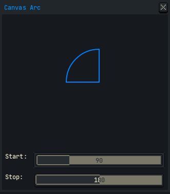
I imagine an arc might be a useful figure for a dialog canvas in the future. Here is some tinkering to draw it with the new graphics context feature in version 1.3-rc1. This isn’t intended to be comprehensive on all the details. It’s a quick experiment to make the search for a how-to shorter and easier.
local function arc(ctx, startAngle, stopAngle, radius, xc, yc)
    local cos = math.cos
    local sin = math.sin
    local tau = math.pi + math.pi
    local halfpi = math.pi * 0.5

    local stAngVerif = math.min(startAngle, stopAngle)
    local edAngVerif = math.max(startAngle, stopAngle)
    local arcLength = math.min(edAngVerif - stAngVerif, tau)

    local arcLen01 = arcLength / tau
    local knCtVerif = math.ceil(1 + 4 * arcLen01)
    local toStep = 1.0 / (knCtVerif - 1.0)
    local invKnCt = toStep * arcLen01
    local handleMag = radius * (4.0 / 3.0) * math.tan(halfpi * invKnCt)

    local cosAngle = cos(-stAngVerif)
    local sinAngle = sin(-stAngVerif)
    local xap = xc + radius * cosAngle
    local yap = yc + radius * sinAngle
    local hmsina = sinAngle * handleMag
    local hmcosa = cosAngle * handleMag
    local cp1x = xap + hmsina
    local cp1y = yap - hmcosa
    local cp2x = 0
    local cp2y = 0

    ctx:beginPath()
    ctx:moveTo(xc, yc)
    ctx:lineTo(xap, yap)

    local i = 1
    while i < knCtVerif do
        local t = i * toStep
        local u = 1.0 - t
        local angle = u * stAngVerif + t * edAngVerif

        cosAngle = cos(-angle)
        sinAngle = sin(-angle)
        xap = xc + radius * cosAngle
        yap = yc + radius * sinAngle

        hmsina = sinAngle * handleMag
        hmcosa = cosAngle * handleMag
        cp2x = xap - hmsina
        cp2y = yap + hmcosa

        ctx:cubicTo(cp1x, cp1y, cp2x, cp2y, xap, yap)

        cp1x = xap + hmsina
        cp1y = yap - hmcosa

        i = i + 1
    end

    ctx:lineTo(xc, yc)
    ctx:closePath()
end

local dlg = Dialog { title = "Canvas Arc" }

dlg:canvas {
    width = 256,
    height = 256,
    onpaint = function(ev)
        local args = dlg.data
        local startDeg = args.startDeg --[[@as integer]]
        local stopDeg = args.stopDeg --[[@as integer]]

        local startRad = startDeg * (math.pi / 180.0)
        local stopRad = stopDeg * (math.pi / 180.0)

        local ctx = ev.context

        local xc = ctx.width * 0.5
        local yc = ctx.height * 0.5
        local w = 64
        local h = w

        ctx.antialias = true

        ctx.strokeWidth = 2.0
        ctx.color = Color { r = 0, g = 127, b = 255 }
        arc(ctx, startRad, stopRad, w, xc, yc)
        ctx:stroke()
    end
}

dlg:slider {
    id = "startDeg",
    label = "Start:",
    min = 0,
    max = 360,
    value = 90,
    onchange = function()
        dlg:repaint()
    end
}

dlg:slider {
    id = "stopDeg",
    label = "Stop:",
    min = 0,
    max = 360,
    value = 180,
    onchange = function()
        dlg:repaint()
    end
}

dlg:show { wait = false }
Variations will depend on whether you want an arc to sweep the shortest path, longest path, etc. You might also expect the start and stop angles to be in [0, 359] or to exceed that range. There is also the question of whether a positive angle is clockwise or counter-clockwise. In terms of appearance, I imagine you could create a stroke only, a chord, a pie slice as above, or a sector with two arcs of different radii connected by a flat end cap. You could also return early with a circle if the start angle and stop angle are 360 degrees apart.
For complex curves, I find it useful to draw diagnostic lines of the control points; or to even create objects for piecewise curves.
There are a lot of primers on the maths of Bezier curves (cubic and otherwise) out there. Much exceeds my own maths understanding. One I’ve found reliable, though, is from pomax (Mike Kamermans):
Cheers,
Jeremy