Hi all,
Below is a demo for how to make a basic easing curve widget with the dialog canvas graphics context in version 1.3-rc, or newer (hopefully).
There’s quite a bit of code, even for a demo. I’m going to plunk it all in one block to make it easier to copy, paste, and interact with. Notes are below.
local function round(x)
    local ix, fx = math.modf(x)
    if ix <= 0 and fx <= -0.5 then
        return ix - 1
    elseif ix >= 0 and fx >= 0.5 then
        return ix + 1
    end
    return ix
end

local function bezierSimplified(cp1x, cp1y, cp2x, cp2y, t)
    -- Unlike a more robust bezier evaluation function,
    -- this assumes that the anchor points are fixed at
    -- (0.0, 0.0) and (1.0, 1.0).
    if t <= 0.0 then return 0.0, 0.0 end
    if t >= 1.0 then return 1.0, 1.0 end
    local u = 1.0 - t
    local tsq = t * t
    local usq3t = u * u * (t + t + t)
    local tsq3u = tsq * (u + u + u)
    local tcb = tsq * t
    return cp1x * usq3t + cp2x * tsq3u + tcb,
        cp1y * usq3t + cp2y * tsq3u + tcb
end

local dlg = Dialog { title = "Basic Easing Curve" }

dlg:canvas {
    id = "easingCurve",
    label = "Curve:",
    width = 256,
    height = 256,
    onpaint = function(event)
        -- Anchor point 1 is assumed to be (0.0, 0.0).
        -- Anchor point 2 is assumed to be (1.0, 1.0).

        -- Constants.
        local cpWidgSize = 8
        local cpWidgHalfSize = cpWidgSize * 0.5
        local swCurve = 1.5
        local swControlStem = 1.0

        local controlStemColor = Color { r = 128, g = 128, b = 128 }
        local curveColor = Color { r = 255, g = 255, b = 255 }
        local cp1Color = Color { r = 168, g = 0, b = 51 }
        local cp2Color = Color { r = 0, g = 132, b = 159 }

        -- Unpack arguments.
        local args = dlg.data
        local cp1x = args.cp1x --[[@as number]]
        local cp1y = args.cp1y --[[@as number]]
        local cp2x = args.cp2x --[[@as number]]
        local cp2y = args.cp2y --[[@as number]]

        -- Clamp x control points to [0.0, 1.0].
        -- Optionally, could clamp y also.
        cp1x = math.min(math.max(cp1x, 0.0), 1.0)
        cp2x = math.min(math.max(cp2x, 0.0), 1.0)

        -- Acquire context.
        local ctx = event.context

        -- Read canvas properties.
        local ctxWidth = ctx.width
        local ctxHeight = ctx.height

        -- Write canvas properties.
        ctx.antialias = true

        -- Convert from real numbers in [0.0, 1.0]
        -- to canvas pixel dimensions.
        -- Invert the y axis.
        local ctxwn1 = ctxWidth - 1
        local ctxhn1 = ctxHeight - 1

        local ap1xPx = 0
        local ap1yPx = ctxhn1
        local cp1xPx = round(cp1x * ctxwn1)
        local cp1yPx = ctxhn1 - round(cp1y * ctxhn1)
        local cp2xPx = round(cp2x * ctxwn1)
        local cp2yPx = ctxhn1 - round(cp2y * ctxhn1)
        local ap2xPx = ctxwn1
        local ap2yPx = 0

        -- Draw control point 1 diagnostic stem.
        ctx.strokeWidth = swControlStem
        ctx.color = controlStemColor
        ctx:beginPath()
        ctx:moveTo(ap1xPx, ap1yPx)
        ctx:lineTo(cp1xPx, cp1yPx)
        ctx:stroke()

        -- Draw control point 2 diagnostic stem.
        ctx.strokeWidth = swControlStem
        ctx.color = controlStemColor
        ctx:beginPath()
        ctx:moveTo(ap2xPx, ap2yPx)
        ctx:lineTo(cp2xPx, cp2yPx)
        ctx:stroke()

        -- Draw curve.
        ctx.strokeWidth = swCurve
        ctx.color = curveColor
        ctx:beginPath()
        ctx:moveTo(ap1xPx, ap1yPx)
        ctx:cubicTo(
            cp1xPx, cp1yPx,
            cp2xPx, cp2yPx,
            ap2xPx, ap2yPx)
        ctx:stroke()

        -- Draw control point 1 square.
        local cp1Rect = Rectangle {
            x = cp1xPx - cpWidgHalfSize,
            y = cp1yPx - cpWidgHalfSize,
            width = cpWidgSize,
            height = cpWidgSize
        }
        ctx.color = cp1Color
        ctx:fillRect(cp1Rect)

        -- Draw control point 2 square.
        local cp2Rect = Rectangle {
            x = cp2xPx - cpWidgHalfSize,
            y = cp2yPx - cpWidgHalfSize,
            width = cpWidgSize,
            height = cpWidgSize
        }
        ctx.color = cp2Color
        ctx:fillRect(cp2Rect)
    end,
    onmousemove = function(event)
        local buttonMouse = event.button
        if buttonMouse ~= MouseButton.NONE then
            -- Unpack mouse even tcoordinates.
            local xMouse = event.x
            local yMouse = event.y

            -- Constants.
            -- Not sure of a better way to get canvas
            -- width and height from within this method.
            -- Maybe make them global variables.
            local ctxWidth = 256
            local ctxHeight = 256
            local hotSpot = 16
            local hotSpotSq = hotSpot * hotSpot

            -- Unpack arguments.
            local args = dlg.data
            local cp1x = args.cp1x --[[@as number]]
            local cp1y = args.cp1y --[[@as number]]
            local cp2x = args.cp2x --[[@as number]]
            local cp2y = args.cp2y --[[@as number]]

            -- Convert from real numbers in [0.0, 1.0]
            -- to canvas pixel dimensions.
            local ctxwn1 = ctxWidth - 1
            local ctxhn1 = ctxHeight - 1
            local cp1xPx = round(cp1x * ctxwn1)
            local cp1yPx = ctxhn1 - round(cp1y * ctxhn1)
            local cp2xPx = round(cp2x * ctxwn1)
            local cp2yPx = ctxhn1 - round(cp2y * ctxhn1)

            -- Test if mouse is near control point 1.
            local xCp1Diff = cp1xPx - xMouse
            local yCp1Diff = cp1yPx - yMouse
            local cp1dSqMag = xCp1Diff * xCp1Diff + yCp1Diff * yCp1Diff
            if cp1dSqMag < hotSpotSq then
                -- Convert mouse coordinate to [0.0, 1.0].
                -- Flip y axis.
                local x01 = xMouse / ctxwn1
                local y01 = (ctxhn1 - yMouse) / ctxhn1

                -- Clamp x coordinate. Optionally, could clamp y also.
                x01 = math.min(math.max(x01, 0.0), 1.0)

                -- Modify number input widgets. Repaint canvas.
                dlg:modify { id = "cp1x", text = string.format("%.5f", x01) }
                dlg:modify { id = "cp1y", text = string.format("%.5f", y01) }
                dlg:repaint()

                -- Return early to prevent case where mouse is near both
                -- control point 1 and control point 2.
                return
            end

            -- Test if mouse is near the control point 2.
            local xCp2Diff = cp2xPx - xMouse
            local yCp2Diff = cp2yPx - yMouse
            local cp2dSqMag = xCp2Diff * xCp2Diff + yCp2Diff * yCp2Diff
            if cp2dSqMag < hotSpotSq then
                local x01 = xMouse / ctxwn1
                local y01 = (ctxhn1 - yMouse) / ctxhn1
                x01 = math.min(math.max(x01, 0.0), 1.0)
                dlg:modify { id = "cp2x", text = string.format("%.5f", x01) }
                dlg:modify { id = "cp2y", text = string.format("%.5f", y01) }
                dlg:repaint()
                return
            end
        end
    end
}

dlg:newrow { always = false }

dlg:number {
    id = "cp1x",
    label = "Control 1:",
    text = string.format("%.5f", 1.0 / 3.0),
    decimals = 5,
    focus = false,
    onchange = function()
        dlg:repaint()
    end
}

dlg:number {
    id = "cp1y",
    text = string.format("%.5f", 0.0),
    decimals = 5,
    focus = false,
    onchange = function()
        dlg:repaint()
    end
}

dlg:newrow { always = false }

dlg:number {
    id = "cp2x",
    label = "Control 2:",
    text = string.format("%.5f", 2.0 / 3.0),
    decimals = 5,
    focus = false,
    onchange = function()
        dlg:repaint()
    end
}

dlg:number {
    id = "cp2y",
    text = string.format("%.5f", 1.0),
    decimals = 5,
    focus = false,
    onchange = function()
        dlg:repaint()
    end
}

dlg:newrow { always = false }

dlg:button {
    id = "confirm",
    text = "&OK",
    focus = false,
    onclick = function()
        -- Draw points along the curve.

        -- Constants.
        local pointCount = 24
        local pointSize = 16
        local pointBrush = Brush {
            size = pointSize,
            type = BrushType.CIRCLE
        }
        local iToLinearFac = 1.0 / (pointCount - 1.0)

        -- Unpack arguments.
        local args = dlg.data
        local cp1x = args.cp1x --[[@as number]]
        local cp1y = args.cp1y --[[@as number]]
        local cp2x = args.cp2x --[[@as number]]
        local cp2y = args.cp2y --[[@as number]]

        local sprite = Sprite(512, 512)
        local spriteWidth = sprite.width
        local spriteHeight = sprite.height
        local sprwn1 = spriteWidth - 1
        local sprhn1 = spriteHeight - 1

        local i = 0
        while i < pointCount do
            local linearFac = i * iToLinearFac
            local x, y = bezierSimplified(cp1x, cp1y, cp2x, cp2y, linearFac)

            local pointColor = Color {
                hue = linearFac * 360.0,
                saturation = 1.0,
                lightness = 0.5
            }

            -- Flip y axis.
            local point = Point(
                round(x * sprwn1),
                round((1.0 - y) * sprhn1))

            app.useTool {
                tool = "pencil",
                color = pointColor,
                brush = pointBrush,
                points = { point }
            }

            i = i + 1
        end
    end
}

dlg:button {
    id = "cancel",
    text = "&CANCEL",
    focus = true,
    onclick = function()
        dlg:close()
    end
}

dlg:show { wait = false }
Notes
There are plenty of explainers on how to evaluate a Bezier curve given the curve’s 2 anchor points, 2 control points and a factor in [0.0, 1.0]. I like these videos:
Coding Math: Episode 19 - Bezier Curves - YouTube
Bézier curves (Coding Challenge 163) - YouTube
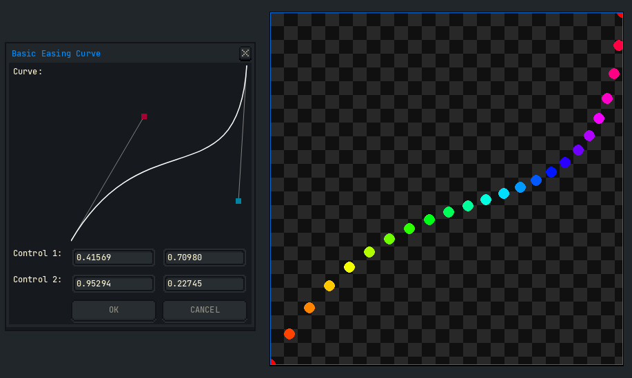
In the screen shot above, the points are not uniformly distributed along the length of the curve. They bunch up in certain sections and stretch out at others. I’m not concerned about that issue for this demo.
I’m using a simplified Bezier curve where anchor point 1 is assumed to be (0.0, 0.0) and anchor point 2 is assumed to be (1.0, 1.0). It’s not intended to be a curve that occurs in 2D space. Rather it’s meant to warp the factor that is supplied to other mixing functions (between colors, frames in time, and so on). That means that evaluation is simplified.
You can see an application for such a curve in creating color swatches at this website:
There are also CSS-focused websites that illustrate the relationship between cubic Bezier curves and animation presets, such as ease-in, ease-in-out, ease-out, etc. For example,
So you could add a combobox widget to this dialog to set a named preset. This would assume that only one cubic Bezier curve is needed to represent the preset.
You could also hide the number widgets by setting their visible property to false and improve the canvas readability by adding a Cartesian grid made of horizontal and vertical lines.
If all numbers could be assumed to be positive, a real number could be converted to an integer with math.floor(0.5 + realNumber). However, if we allow a curve’s control points to exceed the expected range of [0.0, 1.0] and even go negative, math.tointeger does not work the same as casting to int in other languages. Instead math.modf is used to make a round method.
The dialog canvas onmousemove function converts the control points from their actual range in [0.0, 1.0] to the canvas pixel coordinates, where the y axis is flipped. The mouse coordinates are subtracted from each control point to create a vector. The vector’s magnitude squared is compared to a hotspot radius squared to see if the mouse is near the control point. In other words, its Euclidean distance squared is compared to a constant radius. There are any number of variations for how this could be done, including assigning different control points to different mouse buttons.
I imagine that what users really want is a piece-wise cubic Bezier curve where as many anchors and control points could be inserted as they want. I’ve never made one of those before, don’t know all the complexities involved (e.g., avoiding self intersecting curves) and in any case this is only a demo. So that will have to be left for someone who knows what they’re doing. ![]()
Best,
Jeremy